The experimental setup is illustrated in figure 2 .
Figure 2:
The experimental setup.
We logged approximately 20 minutes of synchronized video and laser radar [
8
] data at the HPCC (Honda Proving Center of California) near Mojave. We
then digitized a sequence of 2000 stereo images from the video tapes at
3 frames per second, i.e. every tenth image was digitized. We selected
an initial window surrounding the lead vehicle, although subsequent
processing was completely automatic. In the real-time implementation we
intend to drive visual focus of attention from the output of the laser
radar. Figure
3
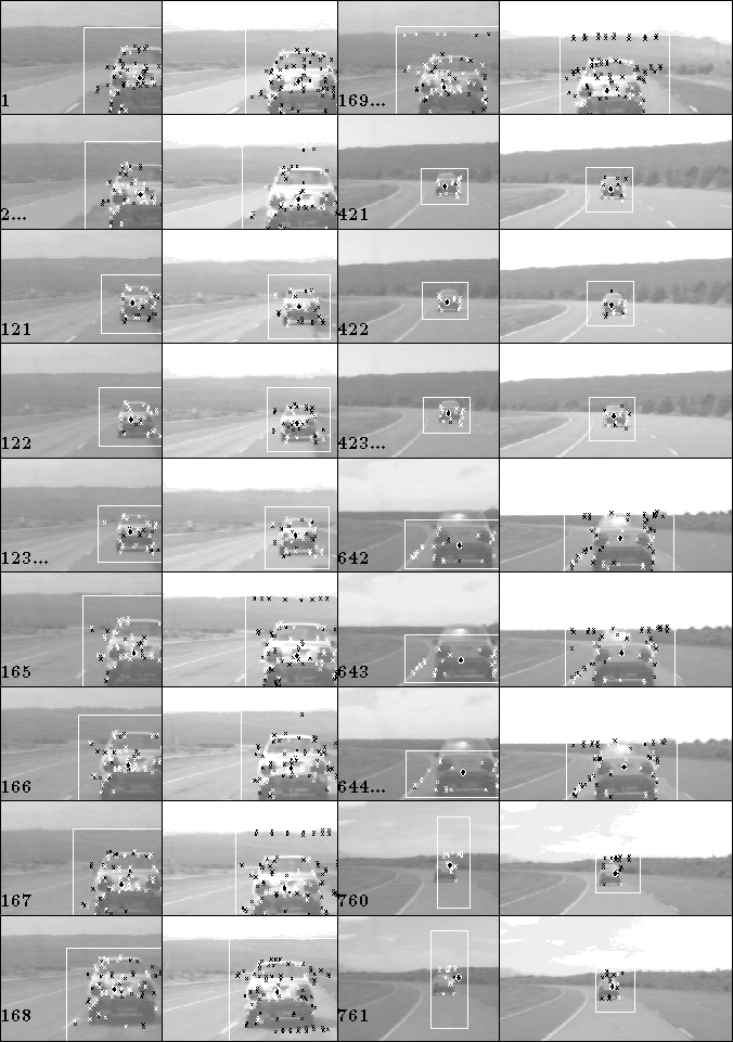
show some example images, with the tracking results superimposed. The
corner features are shown as small crosses, white for those matched over
time or in stereo, and black for unmatched features. The black and white
circle indicates the position of the fixation point, which ideally
should remain at the same point on the lead car throughout the sequence.
The white rectangle describes the latest estimate of the bounding box
for the vehicle, whose size is updated using the diagonal entries in the and
and matrices to estimate the change of scale. We have attempted here to
summarize significant aspects of our data. Images 1 and 2 show the first
stereopairs in the sequence, where the vehicle is close (17m) to the
camera and range estimates from stereo disparity may be expected to be
accurate. By contrast images 121-123 and 421-423 were taken when the
vehicle was 40m and 60m respectively from the camera (the greatest
distances achieved during the sequence). Here we can predict that depth
estimates from stereo will be unreliable, since the disparity relative
to infinity is only a few pixels and so difficult to measure, whereas it
will still be feasible to use the change in apparent size measured by
the motion processing to obtain reasonable range estimates.
matrices to estimate the change of scale. We have attempted here to
summarize significant aspects of our data. Images 1 and 2 show the first
stereopairs in the sequence, where the vehicle is close (17m) to the
camera and range estimates from stereo disparity may be expected to be
accurate. By contrast images 121-123 and 421-423 were taken when the
vehicle was 40m and 60m respectively from the camera (the greatest
distances achieved during the sequence). Here we can predict that depth
estimates from stereo will be unreliable, since the disparity relative
to infinity is only a few pixels and so difficult to measure, whereas it
will still be feasible to use the change in apparent size measured by
the motion processing to obtain reasonable range estimates.
Figure 3:
Example stereo-pairs from the tracking sequence.
Images 165 to 169 illustrate a bumpy section of road where the image position of the car jumps by ten pixels or more between frames. The tracker worked for approximately four minutes before failure, tracking reconstructing the shape and motion over 760 images. Failure was due to a gradual drift in the motion estimates. This is likely to have been caused by the constant interchange between tracked features, which eventually causes the fixation transfer algorithm to drift. This effect can be seen in the later images from the sequence, notably image 642 onwards, where the fixation point in the left image has shifted downwards from its original position on the car, and in the final image 761 the fixation point is about to leave the tracking window, when failure occurs. This drift effect may impose a limit on the time that the tracker may run continuously before being reset.
We computed the range and bearing estimated from the laser range finder and plot them together with corresponding data collected from the vision algorithms in figures 4 and 5 .
Figure 4:
Comparison of range estimates from laser radar and vision.
Figure 5:
Comparison of bearing estimates from laser radar and vision.
Depth from stereo is computed by inverting the projection of the
fixation point at each image pair and finding the closest point of
intersection of the two resulting space rays. The cameras are very
roughly calibrated. The depth/scale ambiguity in the motion estimates is
removed by fixing the depth estimated by motion to be identical to the
stereo measurement at the first frame. We then obtain independent
estimates of depth from motion from the left and right image sequences
as the inverse of the top-left element of (horizontal diagonal element), scaled by the initial stereo depth. This
procedure explains why there is such good agreement between motion and
stereo early in the sequence. As predicted, the stereo depth estimates
become more noisy when the range is large, whereas depth from motion
remains fairly smooth.
(horizontal diagonal element), scaled by the initial stereo depth. This
procedure explains why there is such good agreement between motion and
stereo early in the sequence. As predicted, the stereo depth estimates
become more noisy when the range is large, whereas depth from motion
remains fairly smooth.
The distance to the lead vehicle fluctuates widely in the range from 6m to 60m. Any significant depth change causes the whole feature set to be replaced, and we would suggest that the performance in maintaining track and consistent fixation point transfer over several complete feature set replacements constitutes a significant achievement. However as the sequence progresses, the tracker gradually degrades in performance. This should be expected. In practice one would want to reset the tracker from time to time. It should be noted that the bearing estimates from vision remain good until towards the end of the sequence, when the left image tracker estimate starts to break.
Adrian F Clark